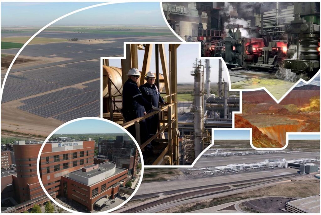

Seven Sectors, Seven Demanding Operating Environments.
Public utility grids are relatively forgiving compared with the far more demanding environments in which MV and HV transformers operate in the private and industrial sectors. There, owners install these transformers both at the point of interconnection and deep inside their facilities, where each unit serves loads, processes, or generation sources that cannot tolerate utility-side constraints or outages.
The following survey examines seven major commercial and industrial sectors.
We’ll discuss why each requires dedicated HV/MV transformers, provide real-world profiles of each, and highlight the operational demands that drive specification and maintenance decisions.
AI Hyperscale Data Centers
Profile Example
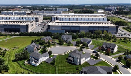
The PowerHouse Pacific Data Center Campus in Sterling, Virginia, illustrates the scale in a single figure: 265 MW of planned IT load on a 43-acre former AOL headquarters site. Northern Virginia as a whole was adding roughly 6.5 GW of data-center capacity through 2025 and is projected to reach 27.5 GW by 2030. The scale is staggering and still accelerating.
Power availability has become the primary binding constraint on new data center development. Data centers consumed approximately 4.4 percent of total U.S. electricity in 2023 and are projected to reach between 6.7 and 12 percent by 2028, a doubling or tripling driven almost entirely by AI workloads. A single hyperscale campus routinely exceeds 100 MW of continuous demand, making dedicated step-down transformer capacity at the utility interface a necessity.
| Typical Data Center Transformer Configuration | |
|---|---|
| Primary Transformer Type | Oil-immersed utility and campus transformers with dry-type distribution transformers inside data halls |
| Typical Voltage Transformation | 115-230 kV stepped down to 12-34.5 kV at the campus level, then 13.8 kV to 480 V for IT distribution |
| Typical Transformer Rating | 20-100 MVA utility transformers and 2-3.5 MVA dry-type distribution transformers |
| Cooling Method | Oil-immersed cooling for utility transformers with air-cooled dry-type transformers serving data halls |
| Deployment Characteristics | N+1 and 2N redundancy architectures are common, with multiple transformers operating in parallel across large campuses exceeding 100 MW |
Private Renewable Energy Generation
Profile Example
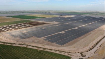
The Vega 5 / Vega SES Complex near Folsom in Imperial County, California, combines 350 MW AC solar PV with 350 MW of battery storage. Projects at this scale place generator step-up (GSU) transformers at the point of interconnection and pad-mounted collection transformers at each inverter or turbine string. This configuration looks straightforward on a one-line diagram but creates a fundamentally different stress profile than traditional utility transmission service.
Solar inverters and wind converters inject significant harmonic content, and the resulting eddy-current losses and localized heating occur at frequencies that accelerate insulation aging are changes that periodic oil sampling can easily miss. CIGRE Working Group A2.62 documented this directly: GSU transformers serving variable renewable generation experience highly intermittent loading and rapid thermal cycling that conventional utility duty cycles simply do not encounter.
Read the case study on how a solar facility used continuous monitoring to detect an H1 bushing anomaly, turning a potential failure into a planned nighttime outage.
| Typical Renewable Energy Transformer Configuration | |
|---|---|
| Primary Transformer Type | Oil-immersed generator step-up (GSU) transformers with additional collection transformers distributed throughout the site |
| Typical Voltage Transformation | 0.4-35 kV stepped up to 110-230 kV for grid interconnection |
| Typical Transformer Rating | 60-120 MVA for main GSU transformers, with additional collection transformers deployed at the inverter or turbine level |
| Cooling Method | ONAN (Oil Natural Air Natural) and ONAF (Oil Natural Air Forced) cooling configurations are most common |
| Deployment Characteristics | Outdoor installation exposed to weather and environmental conditions, typically designed to IP65 standards with transformers distributed across large geographic areas |
Oil, Gas, and Petrochemical Facilities
Profile Example
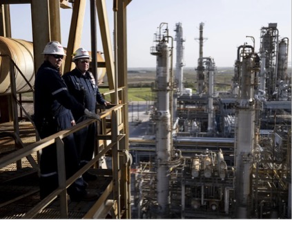
TotalEnergies’ Port Arthur Refinery in Texas is representative of large refining and LNG complexes that maintain multiple on-site substations. These sites typically operate three to ten or more power transformers: a main receiving unit plus process-area substations. Offshore platforms may have only one to three critical units and no alternate supply path at all.
Production shutdown, fire or explosion risk, environmental liability — or some combination of all three — threaten these environments. The atmosphere is corrosive, often remote, and frequently classified as hazardous. Sensor and enclosure requirements therefore differ markedly from standard utility substations; IP66/67 ratings and corrosion-resistant materials are routine, and units must satisfy ATEX or NEC hazardous-area classifications along with seismic ratings where applicable.
| Typical Oil & Gas and Petrochemical Transformer Configuration | |
|---|---|
| Primary Transformer Type | Oil-immersed power transformers serving refinery, petrochemical, midstream, and offshore electrical distribution systems |
| Typical Voltage Transformation | 66-132 kV stepped down to 11 kV or 33 kV for plant-wide distribution and process operations |
| Typical Transformer Rating | 10-60 MVA per unit depending on facility size, process loads, and redundancy requirements |
| Cooling Method | OFAF (Oil Forced Air Forced) and OFWF (Oil Forced Water Forced) cooling systems designed for continuous high-load operation |
| Deployment Characteristics | Often installed in corrosive, hazardous, and remote operating environments where continuous process operation is critical and transformer failures can result in significant production, safety, and reliability impacts |
Heavy Manufacturing and Industrial Plants
Profile Example
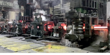
Nucor Steel’s Memphis electric-arc-furnace facility exemplifies the most demanding industrial application. Steel mills, automotive plants, chemical plants, and large food-processing campuses all rely on medium- and high-voltage transformers to serve arc furnaces, large motors, and variable-frequency drives (VFDs). The power quality environment inside these facilities is genuinely hostile.
Electric-arc-furnace duty is the most demanding. A mill typically operates two to five dedicated furnace transformers plus two to four main power transformers.
Furnace units are oil-immersed, 5 to 300 MVA, with primary voltages of 33 to 220 kV and secondary voltages of only 100 to 1,500 V at currents of 10 to 200 kA or higher. High-speed on-load tap changers with 17 or more steps, OFAF or OFWF cooling, and designs that tolerate frequent short-circuit events and severe harmonic distortion are standard. The OLTC is the primary moving part in the transformer, and years of this kind of stress create unique failure modes.
| Typical Heavy Manufacturing and Industrial Plant Transformer Configuration | |
|---|---|
| Primary Transformer Type | Service entrance power transformers supplying manufacturing equipment, production lines, motor control centers, and facility distribution systems |
| Typical Voltage Transformation | 11 kV, 13.8 kV, or 33 kV stepped down to 480 V or 400 V for plant-wide utilization loads |
| Typical Transformer Rating | 500 kVA to 10 MVA, depending on facility size, production requirements, and electrical infrastructure design |
| Cooling Method | Oil-immersed and dry-type transformers are both common, selected based on plant environment, indoor installation requirements, and load characteristics |
| Deployment Characteristics | Facilities frequently experience harmonic distortion from variable frequency drives (VFDs), rectifiers, and high-current motor loads, creating additional thermal and power quality stresses on transformers |
Hospitals and Critical Healthcare Facilities
Profile Example
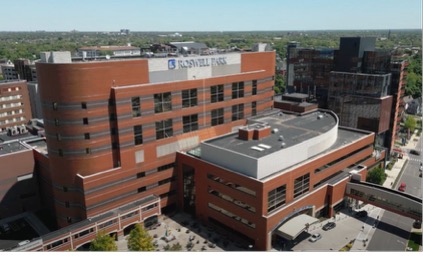
Roswell Park Comprehensive Cancer Center in Buffalo, New York, is typical of large hospital campuses that cannot tolerate any unplanned interruption of surgical suites, intensive-care units, or life-support systems. When a transformer fails at a facility performing tens of thousands of procedures each year, the regulatory and liability question centers on what preventive maintenance measures were in place.
Traditional offline oil sampling requires a complete shutdown, which is typically unacceptable in this environment. Cast-resin transformers generally lack the external condenser bushings of oil-filled units, which means any bushing-monitoring scheme requires accessible MV bushings with capacitance taps. Continuous monitoring is therefore an operational necessity and a documentation requirement: in a liability-conscious environment, the ability to demonstrate that a transformer’s condition was actively tracked carries real institutional value.
| Typical Healthcare and Hospital Campus Transformer Configuration | |
|---|---|
| Primary Transformer Type | Dry-type (cast-resin) transformers serving main utility feeds, emergency power systems, and dedicated critical-care electrical infrastructure |
| Typical Voltage Transformation | 10 kV, 13.8 kV, or 20 kV stepped down to 400 V or 480 V for facility-wide power distribution |
| Typical Transformer Rating | 500 kVA to 2,000 kVA per transformer, with multiple units deployed across large hospital campuses |
| Cooling Method | Air-cooled dry-type (cast-resin) designs preferred for indoor installation, fire safety, and reduced maintenance requirements |
| Deployment Characteristics | Typically configured with N+1 redundancy to support life-safety systems and critical patient care operations, while meeting NFPA 99 requirements and maintaining low operating noise levels of 50-65 dB |
Mining Operations
Profile Example
A large open-pit or underground copper operation in Arizona functions essentially as an electrical island. With no utility backup, the reliability of on-site transformers is existential to continuous production. A transformer failure stops the mine.
Extreme temperature swings, abrasive dust, mechanical vibration, and high-cycle loading from haul trucks and processing mills produce accelerated aging that standard utility duty cycles do not encounter. The isolation of the site compounds the problem: replacement lead times that are already long for any large transformer become even more consequential when the nearest spare is hundreds of miles away and accessible only by a mine haul road.
| Typical Mining Operation Transformer Configuration | |
|---|---|
| Primary Transformer Type | Oil-immersed power transformers serving surface substations, process facilities, crushing circuits, grinding mills, flotation systems, and refining operations |
| Typical Voltage Transformation | 60-138 kV stepped down to 12-34.5 kV at primary substations, with secondary transformers reducing voltage further to 400 V-4.16 kV for plant equipment and process loads |
| Typical Transformer Rating | Up to 40 MVA for primary substation transformers and up to 15 MVA for secondary distribution transformers deployed throughout the operation |
| Cooling Method | Oil-immersed cooling systems designed for continuous-duty operation in demanding industrial environments |
| Deployment Characteristics | Installed in harsh operating environments requiring explosion-proof certification, IP54/IP55 enclosure protection, corrosion-resistant coatings, and seismic ratings suitable for remote, high-altitude, or seismically active regions |
Transportation Infrastructure
Profile Example
Denver International Airport and the Bay Area Rapid Transit system illustrate two distinct transportation loads. Electrified rail corridors place traction-power substations every 10 to 30 km; each substation contains one or two traction transformers, and a regional metro may operate ten to thirty or more such substations. Airports and ports maintain multiple on-site substations serving terminals, runways, ground-support equipment, and navigation aids.
Unplanned outages at traction substations, airport ground-power systems, or port electrification infrastructure halt revenue service and create cascading safety and logistical consequences. Transformer reliability is therefore specified to the same standard applied to life-safety systems in hospitals.
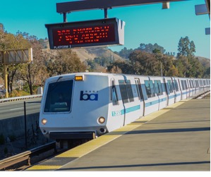
Bay Area Rapid Transit (BART). Traction-power substations for metro systems like BART carry highly cyclical thermal profiles that resemble renewable generation more than steady industrial load.
| Typical Transportation Infrastructure Transformer Configuration | |
|---|---|
| Primary Transformer Type | Oil-immersed traction and receiving transformers serving rail networks, metro systems, airport campuses, and other critical transportation infrastructure |
| Typical Voltage Transformation | 110-230 kV stepped down to 25 kV AC for rail traction systems, converted to 750-1,500 V DC for metro networks, or reduced from 34.5-138 kV to 12-15 kV and ultimately 480 V for airport distribution systems |
| Typical Transformer Rating | 10-60 MVA for traction transformers, 5-30 MVA for airport receiving transformers, and 500 kVA-2.5 MVA for indoor distribution transformers |
| Cooling Method | Primarily oil-immersed cooling for traction and receiving transformers, with dry-type transformers commonly used for indoor distribution in terminal and passenger facilities |
| Deployment Characteristics | Subject to highly cyclical loading from train acceleration, regenerative braking, and peak passenger demand, while maintaining N+1 or 2N redundancy for mission-critical transportation operations and life-safety systems |
The Common Thread
Seven sectors, seven different operating environments. But the same underlying story: the transformer is the final link that converts utility bulk power into the precise voltage, capacity, and reliability profile each industrial process or critical facility demands.
And across all of them, the same three failure locations account for the overwhelming majority of problems: windings and the active part (52 percent of failures), bushings (25 percent), and on-load tap changers (19 percent), according to CIGRE’s 2024 analysis of 848 transformer failures.
Those three components are also precisely where continuous online monitoring — dissolved gas analysis for the main tank, bushing capacitance and power factor tracking — provides the earliest warning. CIGRE and EPRI reliability studies both conclude that nearly 90 percent of transformer failures occur in components observable through online monitoring.